
(a) The electron region geometry for the ammonia molecule is tetrahedral with one lone pair and three single bonds. VSEPR structures like this one are often drawn using the dash-wedge notation. The molecular structure of the methane molecule, CH4, is shown with a tetrahedral arrangement of the hydrogen atoms. However, one of these regions is a lone pair and this lone pair influences the shape of the molecule, giving it a molecular geometry of trigonal pyramidal ( Figure 3).

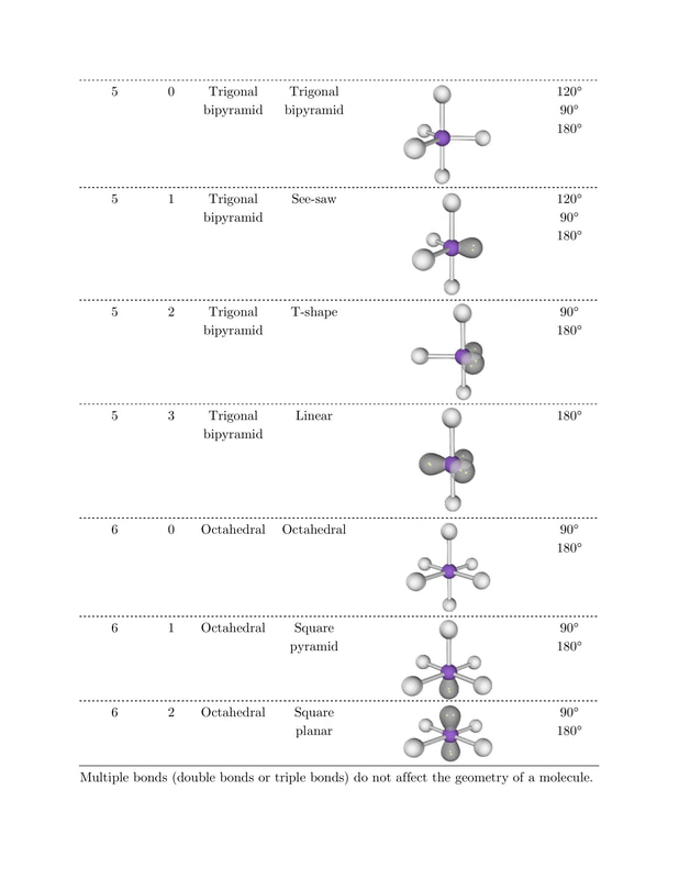
On the other hand, the ammonia molecule, NH 3, also has four electron pairs associated with the nitrogen atom, and thus has a tetrahedral electron region geometry. The electron region geometries will be the same as the molecular geometries when there are no lone pairs of electrons around the central atom, but they will be different when there are lone pairs present on the central atom.įor example, the methane molecule, CH 4, which is the major component of natural gas, has four bonding pairs of electrons around the central carbon atom the electron region geometry is tetrahedral, as is the molecular geometry ( Figure 2). Molecular geometry describes the location of the atoms, not the lone pairs of electrons. Bonds and lone pairs are treated equally. The electron region geometries shown in Table 1 describe all regions where electrons are located. It is important to note that electron region geometry around a central atom is not the same thing as its molecular geometry. Number of Electron DomainsĮlectron Region Geometry versus Molecular Geometry Table 1: The basic electron region geometries predicted by VSEPR theory maximize the space around any region of electron density (bonds or lone pairs). Two regions of electron density around a central atom in a molecule form a linear geometry three regions form a trigonal (or triangular) planar geometry and four regions form a tetrahedral geometry. Table 1 illustrates electron region geometries that minimize the repulsions between regions of high electron density (bonds and/or lone pairs).

The BeF 2 molecule adopts a linear structure in which the two bonds are as far apart as possible, on opposite sides of the Be atom. The F-Be-F bond angle is 180° ( Figure 1) in the BeF 2 molecule resulting in a linear geometry. With two bonds and no lone pairs of electrons on the central atom, the bonds are as far apart as possible, and the electrostatic repulsion between these regions of high electron density is reduced to a minimum when they are on opposite sides of the central atom. The Lewis structure of BeF 2 ( Figure 1) shows only two electron pairs around the central beryllium atom. The electrostatic repulsion of these electrons is reduced when they assume positions as far away from each other as possible.Īs a simple example of VSEPR theory, let us predict the structure of a gaseous BeF 2 molecule. The electrons in the valence shell of a central atom form either bonding pairs or nonbonding lone pairs. The VSEPR model assumes that electron pairs in the valence shell of a central atom will adopt an arrangement that minimizes repulsions between these electron pairs by maximizing the distance between them. Valence shell electron-pair repulsion theory (VSEPR theory) enables us to predict the molecular geometry, including approximate bond angles around a central atom, of a molecule from an examination of the number of bonds and lone electron pairs in its Lewis structure.

| Key Concepts and Summary | Glossary | VSEPR Theory


 0 kommentar(er)
